Visual glossary for phase-field fracture
This page is a visual companion to the phase-field primer. It focuses on
the terms that usually slow down first-time users: energy splits, AT1 versus
AT2, and the regularisation length scale l0.
Why this page exists
The continuum equations in Physics, units, and formulation and the phase-field primer are the right place for the mathematics. This page provides a compact visual guide:
AT1 vs AT2: how the local crack-density term changes nucleation.
Energy splits: why compressive energy should not be degraded.
Length scale
l0: how a diffuse crack band replaces a sharp crack.
Energy splits in bending
The schematic below compares two common choices for the degraded elastic energy. The left panel shows the problem with degrading the full energy: damage can appear in a compressed region. The right panel shows a spectral split, where only the tensile part of the strain energy is degraded and the crack follows the tensile notch tip.
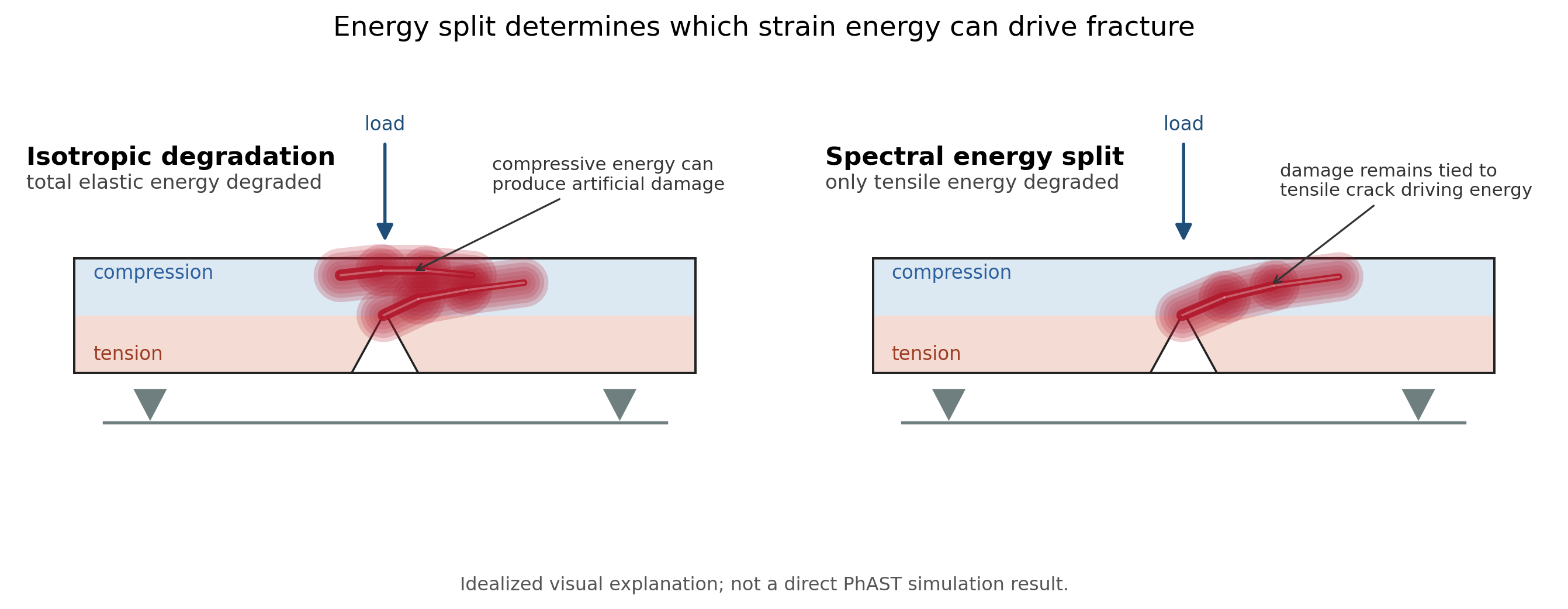
Conceptual comparison of phase-field damage under bending for two elastic energy formulations. Isotropic degradation lets the total strain energy drive damage and can therefore accumulate damage in a compressive zone. A spectral split restricts the driving force to the tensile strain contribution. This diagram is an idealized explanation and is not a direct PhAST simulation result.
AT1 and AT2 at a glance
The local dissipation density is the other common source of confusion. The table below summarizes the public choices in PhAST.
Model |
Local term |
|
Visual interpretation |
|---|---|---|---|
AT1 |
|
|
Damage stays at zero until a threshold is reached. |
AT2 |
|
|
Damage can begin smoothly once the crack driving field is nonzero. |

The plot compares only the local dissipation term. The full crack-surface
density also includes the gradient penalty and the normalization constant
c_w.
What the regularisation length scale does
The length scale l0 controls how wide the diffuse crack band becomes.
Smaller values give a narrower band and a sharper transition, but they require
finer meshes. In practice, the mesh spacing near the crack should be fine enough
to resolve the diffuse band.
As a rule of thumb, the public fracture examples are written so that users can
see the relationship between l0, mesh density, and the visible damage field
directly in the result plots.